Electrical Shaft CAD Layout with 152 cm Service Panel Details
Description
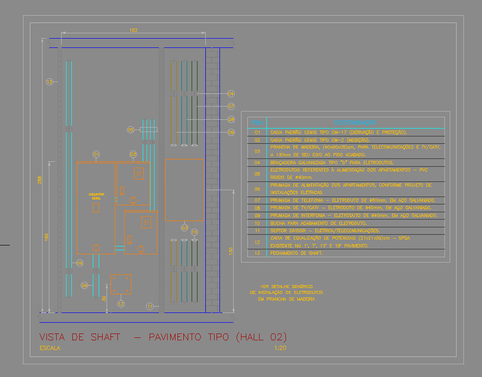
This AutoCAD DWG file features a precisely drafted electrical and telecom shaft layout for a typical floor level, showcasing all essential service elements within a 152 cm-wide shaft structure. The drawing includes accurate placements of CM-17 and CM-2 electrical boxes, PVC conduits for apartment power distribution, galvanized steel brackets, wooden telecom board panels measuring 40×80×0.8 cm, and TV/CATV feed lines. Each component is dimensionally marked, with clear routing paths for electrical, telephone, grounding, and intercom lines shown through vertical and horizontal conduits. The shaft layout also highlights detailed spacing indicators, mounting positions, and service access areas to support installation accuracy.
A comprehensive item table is included on the right side of the drawing, listing conduit specifications such as 40 mm PVC conduits, Ø50 mm galvanized conduits, grounding equalization boxes sized 21×10×4 cm, and dedicated feed lines for each apartment. The DWG also distinguishes between electrical, telecommunication, and SPDA grounding elements, enabling engineers to coordinate multi-service routing efficiently. This layout is ideal for electrical engineers, MEP designers, and contractors who require accurate shaft detailing for high-rise residential or commercial projects. The file supports precise planning, clash detection, and compliance with installation standards.

Uploaded by:
Eiz
Luna
